 This insightful blog post was developed by Fagor Automation and made available to DMS users as part of our cooperative partnership.\ In some circles, the mere mentioning of the word “accuracy” will create an awkward silence. Despite this, accuracy is more of a concern than ever before. Applications requiring acute accuracy not just on individual applications, but uniformed applications that tie together has become commonplace. For over 30 years now, the traditional offered linear compensation tables have been the final solution to providing machine tool accuracy. However, to achieve a more a global accuracy as frequently required within the aerospace industry, these conventional compensation tools are insufficient considering they do not take into account the machine’s kinematics and other factors related to the mechanical and electrical relationship between the multiple combinations of axes of motion.
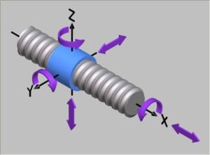
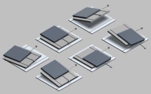 Therefore, the conventional compensation tools must be complemented with more advanced tools that adapt to the different designs of the machine and their specific kinematics. In steps, the feature called Volumetric Compensation. Which then brings the obvious question to ask ourselves, has Volumetric Compensation become an industry-accepted method for enhancing both the accuracy and performance of a machine tool? We know that misalignments, necessary clearances, and imperfections during the manufacturing and assembly of a machine tool are realities that cannot be avoided. But with the assistance of Volumetric Compensation, can we minimize these errors? To find the answers, the first thing we have to do is identify where the actual problems derive from. With your typical Machining Center, the below-pictured table errors can be seen. Every machine on varying levels contains error within these quadrants of motion. Your typical Spindle articulation errors can be seen in the two illustrations.
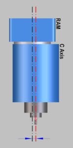
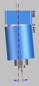
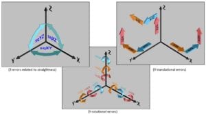 Based upon the configuration of the machine, we know you can have 6 different types of potential errors. 3 Angular (purple) 2 Straightness related (pink) 1 Linear (yellow) The blue arrow represents the movement of the axes which needs to be compensated. Extending this study to the complete machine, the machine volume is represented by the X, Y and Z axes. The combination of these axes increases the possibility of errors to 21 different types. As seen by the above graphics, we have determined that we have 3 errors related to straightness, 9 rotational error possibilities and 9 translational error possibilities. We then now know we have up to 21 degrees of freedom that require error mapping. Once identifying the problem, the real question becomes… How easy is it to compensate for these machine deficiencies?
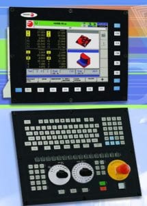
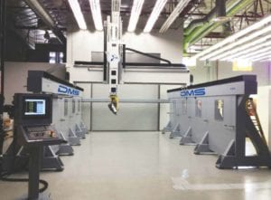 The Fagor 8070 is designed to be a solution for high performance applications. The CNC runs an industrial hardened Windows ® platform utilizing Pentium technology. The 8070 has true 5 axes machining compensation capability (RTCP). This solution increases productivity while maintaining part finish accuracy. Optimizing high-speed block processing speeds and analyzing the tool path with advanced block look ahead simultaneously results in an optimum part finish. Tool path transitions are enhanced with a predictive control feature that applies a carefully calculated acceleration control for each machining operation. Mechanical stress is reduced by applying post-interpolation filters that eliminate the resonance frequencies common to high-speed machines. In addition, for optimum accuracy, the 8070 is capable of the Volumetric Compensation feature. Additional capability includes up to 4 execution channels with a total of 28 axes plus 4 spindles. To perform the data collection process, API Services out of Newport News, VA was called upon. API utilizes the XD™ laser system to error map all 21 degrees of freedom of the machine tool. As stated by Art Kietlinkski, Project Manager, “The XD™ Laser has a 6D sensor that is capable of collecting all 6 degrees of freedom for each axis in one easy set-up. The laser system also comes equipped with special optics for readily capturing the three squareness errors, therefore completing the 21 error table mapping.” The measurement process is simple in that you set your laser and perform a baseline measurement test of the squareness of the machine. Then, utilizing a simple G-code program for each axes that steps in increments across the entire travel, we capture the positional data at each increment. Each run of the X,Y & Z axes generates 6 tables of error data to complete 18 of your required error map tables. When completed with all axes, you then re-laser for squareness to generate your 3 square-ness error tables. After data collection is complete, you then simply transfer the tables to the Fagor CNC and re-run the laser to verify your results. Activating the tables is easily done with a quick CNC Machine parameter change. Additional fine-tuning can be done as needed for each axes based upon the comparative results. What did we learn? As per the charts, Fagor Volumetric Compensation (FVC) has shown us a quantified 50% increase in precision. These types of accuracy increases do not just increase precision, but also machine part finish & quality based upon the idea that tools are actually removing metal at their designed rate. X-axis first 3 results -tables (pitch, straightness Y, straightness Z)

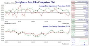
Z axis first 3 results -tables (pitch, straightness X, straightness Y)
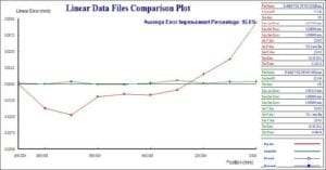
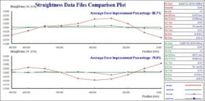
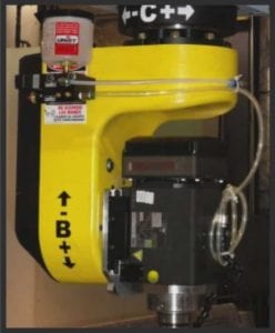 (These types of accuracy improvements are not possible without this technology.) Another aspect taken into effect with Fagor Volumetric Compensation is temperature. Your typical machine shop environment varies throughout the day and so does the machine temperature depending on the machine utilization. Because of this, a machine tool may expand or contract altering the calculated compensation values. To compensate, the Fagor 8070 CNC offers up to 4 separate volumetric compensation tables to make corrections at four different temperature levels. This helps maintain consistent part quality regardless of what temperature variances you may have. These tables may also be used to apply different compensations depending on mechanical devices that may have been installed temporarily on the machine. For example, if a machine uses interchangeable articulated spindles, the compensation tables may be configured accordingly for each individual spindle. (The image is of a DMS Heavy Duty Cast Iron Yoke – HSK Spindle.) New innovations such as Volumetric Compensation by Fagor Automation help provide solutions for modern aircraftdesign and similar long-term global projects. The processes utilized by aerospace manufacturers require a standard of measurement and method of evaluation beyond what has been available in the past. We’re proud to be in partnership with this global cooperative. So, we ask – has Volumetric Compensation become an industry-accepted method for enhancing both the accuracy and performance of a machine tool? The answer is yes. Myth confirmed.
The Manufacturing Minute is our monthly enewsletter. We deliver the latest manufacturing industry news, updates on DMS events, and the latest content from our blog. Subscribe today to stay in the loop on what's happening in manufacturing and at DMS.